Matchless Info About How To Draw Velocity Triangles
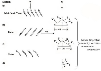
12.5 Velocity Triangles For An Axial Compressor Stage

How To Draw Velocity Diagram Using Relative Method With Animation - Part Ii Youtube
Velocity Triangles In Turbomachinery

How To Draw Velocity Triangle | Step By Procedure In Tamil Hydraulic Turbines| Impact Of Jet - Youtube
Impulse And Reaction Turbines - Machines Fluid Mechanics Engineering Reference With Worked Examples

How To Draw A Velocity Triangle For Various Pumps Or Turbines - Quora

The velocity triangle is the vectorial representation of kinematic movement.
How to draw velocity triangles. The absolute flow enters at 25o with the blade angles as shown. P3.23 for the mechanism shown. This determines whether we have a turbine or.
How to draw velocity triangles for turbomachines. About press copyright contact us creators advertise developers terms privacy policy & safety how youtube works test new features press copyright contact us creators. The flow rate is 8 m3/s of water at 20°c.
In turbomachinery, a velocity triangle or a velocity diagram is a triangle representing the various components of velocities of the working fluid in a turbomachine. A vector is a directional magnitude. A general velocity triangle consists of the following vectors:
How to draw velocity triangles for turbomachines. One of the blade velocities must be zero. Impulse and reaction turbines turbines machines.
An idealized radial turbine is shown in fig. Drawing / by perfect answer. This relationship is illustrated in the velocity parallelogram of.
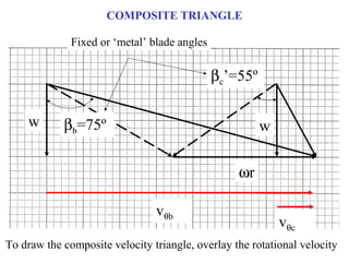
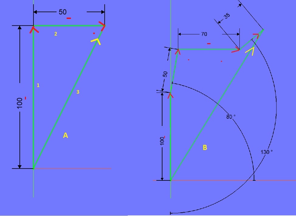
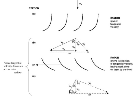
Enter all the desired parameters and hit set rows. An example of a velocity triangle drawn for the inlet of a turbomachine. C draw velocity triangles assuming that wr = 2 times the axial velocity w (w = constant) velocity triangles at b.

Tricks : Axial Compressor || Velocity Triangle Propulsion - Youtube

How To Draw Velocity Diagram (part 1) - De Laval Impulse Steam Turbine Youtube
How Can I Draw Velocity Vector Diagrams? | Socratic
12.6 Velocity Triangles For An Axial Flow Turbine Stage
How To Draw Velocity Diagram & Analysis Of Mechanism - Theory Machines Mechanisms Youtube
How To Draw A Velocity Triangle For Various Pumps Or Turbines - Quora
File:fluid Velocity Triangle.gif - Wikipedia

Fluid Mechanics - Can Someone Please Give Me A Hint On How To Draw Velocity Triangles For This Specific Inward Flow Reaction Turbine Problem? Engineering Stack Exchange

Velocity Triangles In Fluid Mechanics And Machinery | Unsymmetrical Vane Turbomachinery - Youtube

How To Draw Velocity Diagram (part 1) - De Laval Impulse Steam Turbine Youtube

The Generated Inlet And Exit Velocity Triangles At Rotor Mean Line Fig.... | Download Scientific Diagram

File:velocity Triangles For An Inward-flow Radial (ifr) Turbine Stage With Cantilever Blades.jpg - Wikimedia Commons

Construction Of Inlet And Outlet Velocity Triangle | Impact Jet Hydraulics Fluid Mechanics - Youtube
